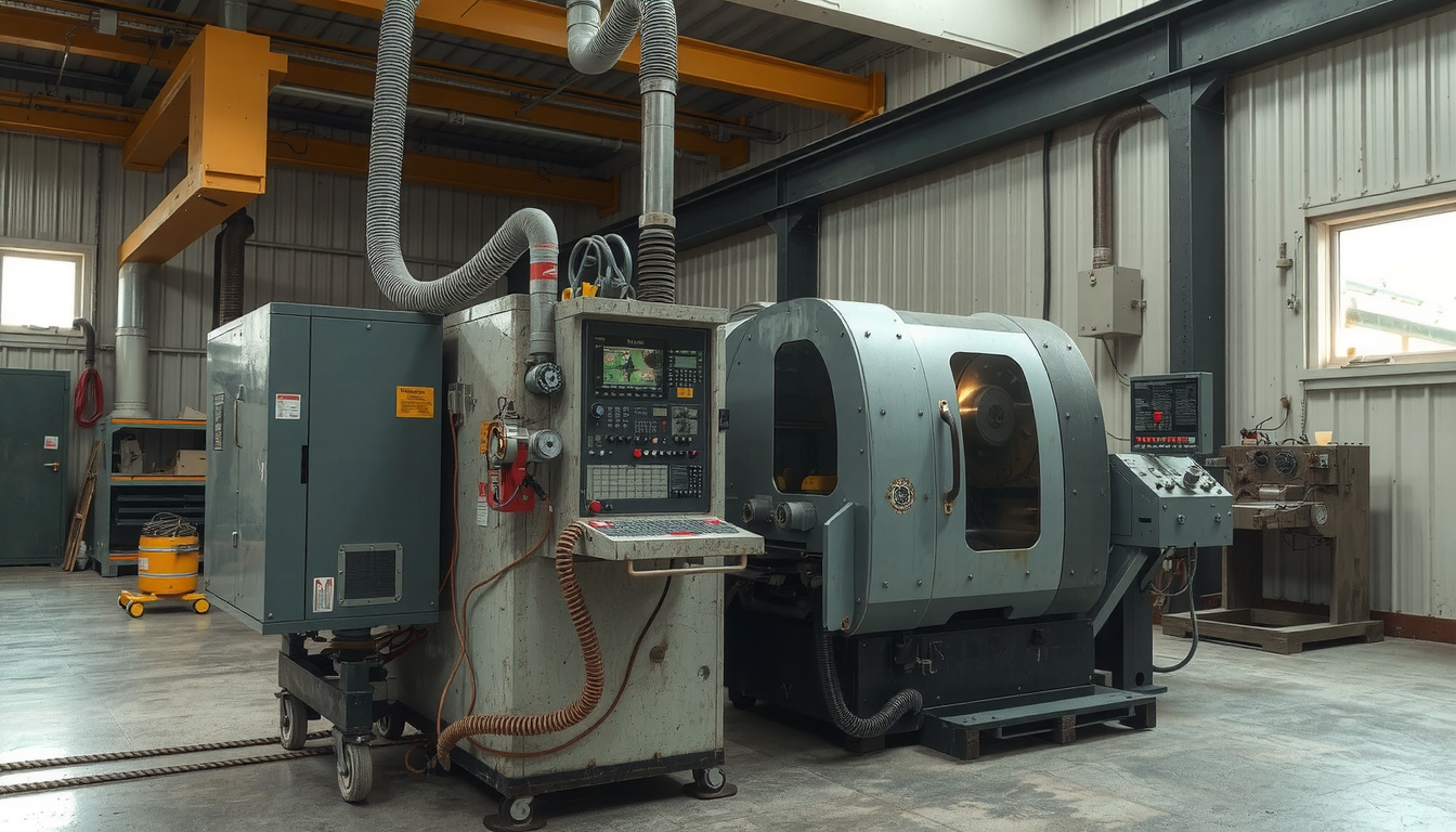
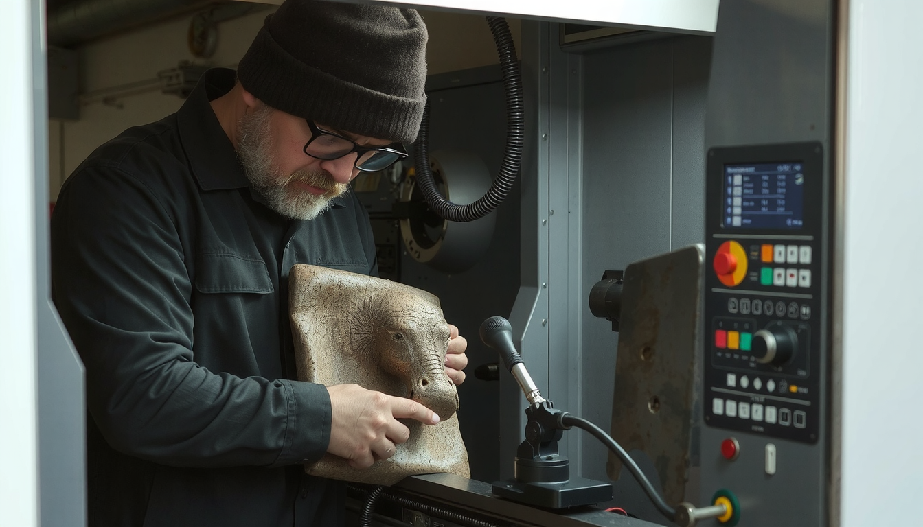
It can be a big job to set up a CNC lathe for a new task, but it is a skill learned by every machinist. Like any complex job, we can simplify it into clear, small steps.

This manual will demonstrate the way to set up a CNC lathe from the starting point to the end of the process. From a powered-off state to a completed part, we will walk you through the entire process. This ability is necessary for a modern machinist.
We will explain the six main steps of the process, which are: 1. Preparation and Safety, 2. Machine Homing, 3. Tooling, 4. Workpiece and Offsets, 5. Program Loading, and 6. The First Cut. If you follow these steps in this order, you will achieve a safe and successful setup.
Discover more on precision manufacturing by partnering with Mékalite, a trusted company that offers comprehensive knowledge and services in the sector.
Phase 1: The Essentials of Pre-Setup – Safety and Workspace Preparation
Before we press the button to turn the machine power on, we should be sure that everything is safe. A safe setup is a smooth setup. These initial checks are the best way to prevent accidents and wasting money. Getting these basics right is a fundamental part of how to set up a CNC lathe in an accurate manner.
Personal Protective Equipment (PPE) is a Must
Your safety is the number one priority. Always wear the proper equipment before you get to work in the machine area.
- Safety glasses with side shields are mandatory.
- Close-toed, steel-toed boots are a must.
- Absolutely no loose clothing, hoodies with strings, or other things that can get hooked up.
- All jewelry should be removed, including rings and watches.
- Securely tie your long hair back.
Understanding Your Machine
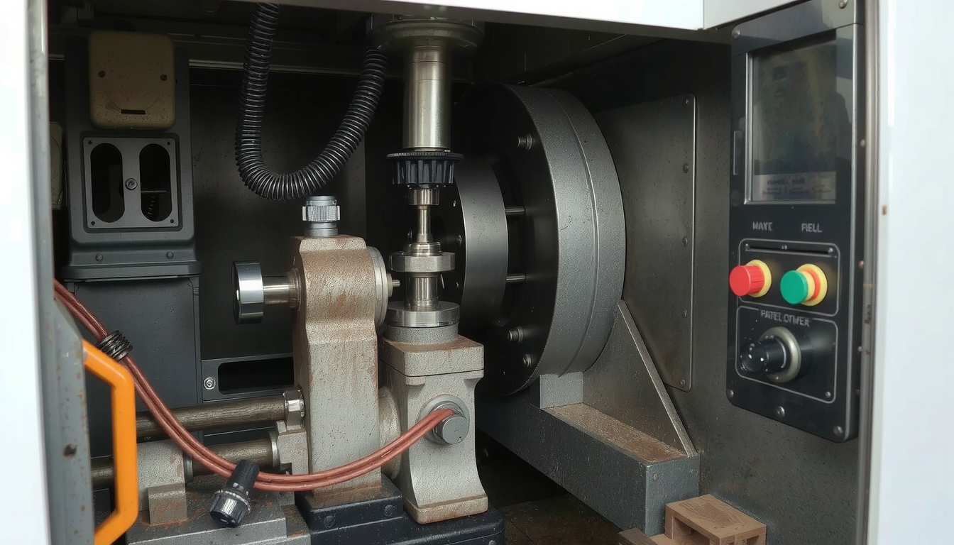
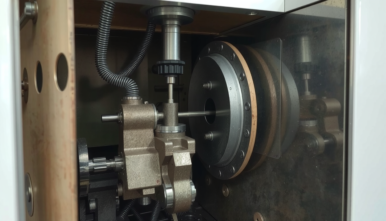
You need to have knowledge about the machine’s major parts. Right after you start your inspection, check for the Control Panel, the Chuck (the device that holds the part), the Turret (the holder for the tools), and the Tailstock.
But the most important part is to identify the Emergency Stop button, or E-Stop. In our factories, before any new operators do anything, they first have to press the E-stop button. This helps them to feel and note the position of it. It is a memory of the E-stop that your muscles will be grateful for later in a real emergency.
Cleaning the Workspace and the Machine
A machine that is clean is a machine that is precise. Chips and dust from the last job can lead to errors. They can prevent tools and your workpiece from sitting flat. That will not be good for your project.
Wipe the turret faces, the jaws of the chuck, and the inside of the machine. Also, make sure you have checked the fluid levels on the machine. The coolant, hydraulic fluid, and way lube should all be at the right levels.
Phase 2: Powering Up and Homing the Machine (Finding Machine Zero)
Now that we have finished our safety checks it is the time to turn on the machine. This phase is about the correct way of powering up and “homing” the machine. Homing is what tells the machine where its axes are positioned in space.
Follow the Sequence of Correct Power-Up

The machines need a startup sequence that is quite specific. Adherence to it will keep you away from errors and alarms.
- Turn on the main power disconnect. This is usually a large switch at the back of the machine.
- Press the “Power On” button on the control panel.
- Wait for the machine’s computer, the controller, to fully boot up.
- Clear any alarms that appear on the screen. Often, this is done by twisting and releasing the E-stop button if it was pressed.
Finding Machine’s Axes (Homing or Zero Return)
It is now time to home the machine. This moves the machine’s moving parts (the X and Z axes) to their fixed position. This position is called “Machine Zero.” This is the point of the machine from which it computes all measurements.
The procedure is generally straightforward. Choose the “Zero Return” or “Home” mode at the control panel. Then you will press the button for the X-axis, and then the Z-axis. The machine will move until it hits its home switches.
As we learned in the reports from people who set up a lathe for the first time, the key is patience. If the machine doesn’t work as you expect, stop. Refer to the machine manual to see the correct steps before starting.
Phase 3: Setting Tooling
This is one of the most important topics in our guide about how to set up a CNC lathe. In this section, we will mount the cutting tools in the turret and then measure their exact positions so the machine can know their location.
Preparing and Loading Tools into the Turret
First, make sure that both the tool holders and turret pockets are clean. Any small chip can throw off your tool’s position, causing inaccurate parts.
Mount each tool into the holder first and tighten it firmly. Next, load the tool holders into the right places on the turret. Follow your setup sheet or plan. For example, Tool 1 might be a roughing tool, and Tool 3 might be a finishing tool. Make sure to fully tighten them when the turret is loaded with tools.
Understanding Tool Offsets: Geometry and Wear
A tool offset is nothing else than a way of telling the machine the exact size and position of each tool tip. Without this information, the machine has no idea where the cutting edge is located.
We have two types of offsets mainly used. The “Geometry” offset is the principal measurement. It implies the distance from Machine Zero up to the tool tip. On the other side, the “Wear” offset is for making very small changes during a job, usually to hold a tight size.
How to Set Tool Offsets: A Practical Walkthrough
There are many methods which we can use for measuring tools. In many modern workplaces, a tool presetter is a common application. It is a device that measures tools for a machine, off the machine. Here, we will just describe the common “manual touch-off” method.
This method is a basic skill necessary for any CNC lathe setup.

- Manual Touch-Off Steps:
- Use the control panel to move a tool (e.g., Tool 1) close to the workpiece.
- Carefully jog the tool until its tip just touches the face (the flat front) of the part. This will set your Z-axis.
- Go to the “Offset” page on the controller. Find the line for Tool 1.
- Move the cursor to the Z Geometry column. Use the controller’s function, like “Z Face Measure,” to record the position. The machine will now know where the tip is in the Z-axis.
- Next, carefully jog the tool to touch the outside diameter of the part. This will set your X-axis.
- On the same offset page, move to the X Geometry column. Tell the machine the diameter you just touched (e.g., “X 50.0 Measure”). The machine now knows the X position.
- Repeat this process for every tool you will use in the program.
A common example of an offset page is below depending on the tools applied.
| Tool No. | X Geometry | Z Geometry | Radius | Tip |
|---|---|---|---|---|
| 1 | -150.123 | -55.456 | 0.8 | 3 |
| 3 | -148.789 | -57.991 | 0.4 | 3 |
| 5 | -175.330 | -70.125 | 0.0 | 8 |
Phase 4: Workpiece Securing and Inputting Part Zero
Having done the measuring, we now mount our raw material. We also need to tell the machine where that material is. This is called setting “Part Zero.”
Selecting and Employing Your Workholding
Workholding is the device that grips your material. The most common type on a lathe is a 3-jaw chuck. You can also use a collet chuck for smaller or more precise work.
Check your workpiece if it is well clamped in the jaws. It should be able to resist the cutting forces due to good clamping. Also, look if the part is running true, in other words, if it spins with very little wobble.
The Idea of Part Zero (G54 Work Offset)
This is a point that often confuses new operators. The machine has its own “Machine Zero.” But your program needs its own zero point, which we call “Part Zero.” This is the 0,0 point for your G-code program.
Think of it this way: Machine Zero is where the machine lives. Part Zero is where your part lives for this specific job. We store this location in a “Work Offset,” usually called G54. This makes the entire process of how to set up a CNC lathe much more flexible.
Setting the Z-Axis Part Zero
The Z-axis Part Zero is typically the finished front face of the part. To set it, we simply bring a known tool and touch it to the front face of our raw material.
On the controller, go to the Work Offset page (G54). Select the Z-axis column. Use a function like “Z Face Measure” to tell the machine that this position is Z0. The machine will calculate the G54 value automatically. It does this by using the tool offset and the current machine position.
Setting the X-Axis Part Zero
In a lathe, this process is far easier. The X-axis Part Zero is always the centerline of the spindle. The machine is constructed in such a way that it knows where this point is. As long as your X-axis tool offsets are correct, the machine will handle X0 automatically.
Phase 5: Program Loading and Verification

The physical setup has been completed and now we need to load our G-code program and check it for safety. This is a step that prevents a machine crash. So always avoid hitting the “Cycle Start” button on new setups.
Transferring the G-Code Program to the Machine
The program file has to be transferred from your computer to the machine’s controller. Popular methods include using a USB flash drive or a network (Ethernet) connection. Some older machines might still use an RS-232 connection.
Don’t Start! The Safety Before Cutting
Before we cut any metal, we use the machine’s own tools to do a “pre-flight check.” These safety features are your best friends.
- Graphics Mode: This draws the toolpaths on the screen. You can watch a simulation of the program to see if the tools move where you expect them to.
- Dry Run: In Dry Run mode, the machine will perform all the program’s moves, but the spindle will not turn and the coolant will not come on. This is a great way to check that the tools will not crash into the chuck or tailstock.
- Single Block: When this mode is active, the machine will only run one line of code each time you press Cycle Start. This gives you total control to check each move.
- 5% Rapid Override: Turn the rapid override knob down to its slowest setting (e.g., 5%). When you start the program, the tools will approach the part very slowly, giving you time to react if something is wrong.
This process of simulating and running programs safely is the most important practice for all professional machinists. It guarantees that the digital program is operational in a real-world machine.
Phase 6: Making the First Cut and Fine-Tuning
We have passed all checks. It is time to make the first part. This is the last step in learning how to set up a CNC lathe.
Starting the First Part Safely
We pay special attention to the safety of running our first part.
- Ensure that all machine doors are closed.
- Turn the Rapid and Feed Override knobs down. A good starting point is 25% for rapids and 50% for feeds.
- Keep your hand near the “Feed Hold” button, not the E-Stop. Feed Hold will pause the machine, while E-Stop will require a full restart.
- Use Single Block mode for the first few lines of code for each new tool. This lets you watch its first approach to the part.
- Watch the “Distance to Go” display on the screen. It tells you how much further the tool has to move, which helps you anticipate its path.
Inspecting the Part and Making Adjustments
Once the program is over, you can safely open the doors, remove the part, and clean it. Use calipers or micrometers to measure the important sizes.
Let’s say a diameter needs to be 50mm, but it measures 50.1mm. It is 0.1mm too big. We can fix it quickly and easily. Go to the “Wear Offset” page for the tool that cut that diameter. In the X-wear column, enter -0.1. The machine will then adapt the tool’s path to produce the part at the right size.
From Setup to Production
The moment you make one piece of excellent quality, the setup becomes validated. You can now turn your overrides back to 100%. You are set to run the rest of your parts.
If you are looking for scaling production or need highly complex parts machined, considering professional Services de tournage CNC can be a smart move.

