A CNC lathe is a motorized machine that functions automatically. The ends are formed with the materials tossed and frayed off the outside of a cutting tool. This is the inverse “additive” method. The raw material is removed and thus the final part is created.

The process is founded on a computer. Computer Numerical Control is what CNC stands for. The primary vehicle of this computer control marks the distinction among modern CNC lathe and traditional, manual lathe. The key difference in the automation and precision that CNC provides is obvious. This piece will be the clarifier of the full operation; a CNC Lathe machine is programmed, set up, and run.
The Central Principle: What is Meant by CNC Lathe
The main idea is very basic. An item that you could picture in your head is a potter’s wheel. The clay wheel is rotated and the potter shapes it with his hands. A CNC lathe has a similar approach. But it operates on more durable materials.
The work material is where the raw material is referred to as. It is kept and turned at a high speed. The cutting tool then shifts against the spinning workpiece which is the motion of the tip of the well-chosen tool. The working material of wood is then proceded to where it is shaped in the desired image. The most common term for this method is CNC turning.
A standard CNC lathe features two primary axes of movement. These parameters are known as axes.
* The Z-axis is the motion in the direction of the length of the workpiece.
* The X-axis is a direction inwards and outwards from the workpiece. This motion decides the diameter as the part.
A CNC lathe is not the same as a mill. In a mill, the cutting tool actually spins and moves. The workpiece often does not move. Hence the difference is easier to see how does an cnc lathe machine work.
Outline of a CNC Lathe Machine
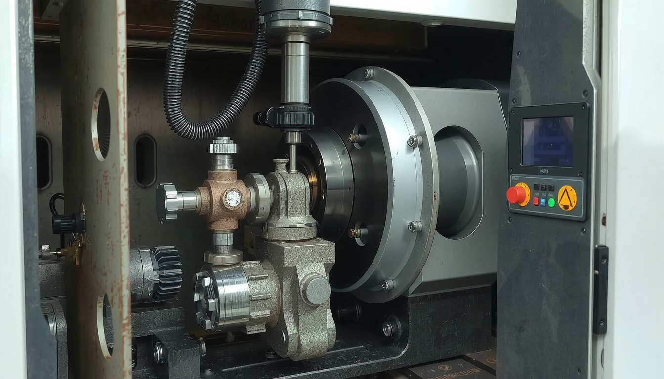
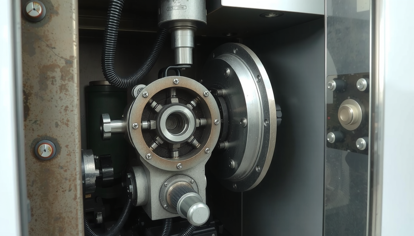
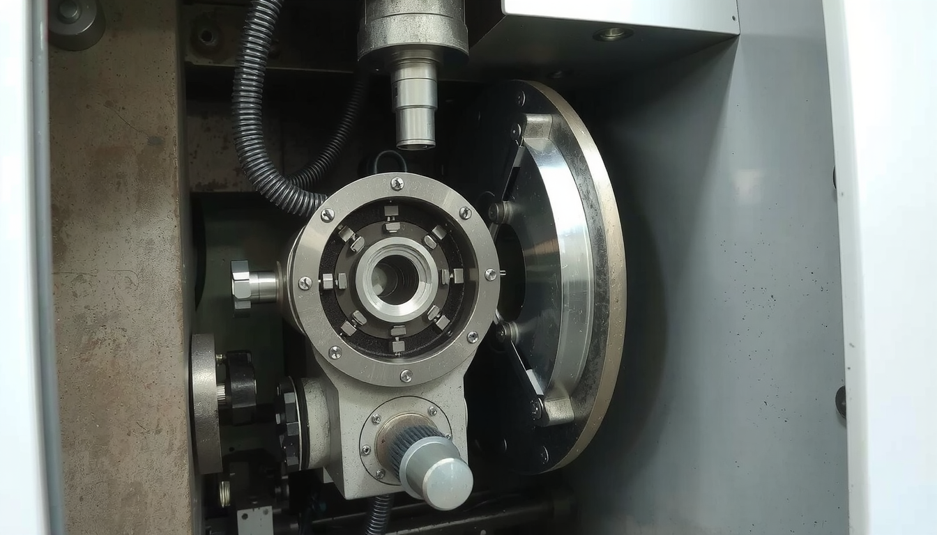
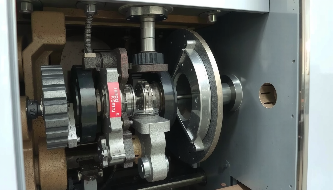
To comprehend how a CNC lathe operates, it is essential to be acquainted with its individual components. Every section has a specific role in the machining operation. Familiarizing yourself with these various parts and their roles is the key to getting a grasp of the more general view.
The key components of a classic CNC lathe are:
- Headstock
The power unit of the machine. It embraces the principal motor and the spindle. This segment provides the drive for the rotation of the workpiece. - Broche
The rotating shaft that contains the workpiece. It spins at very high, controlled speeds.

- Chuck (or Collet)
This device is mounted on the spindle. It is a powerful clamp that holds the raw material securely in place while it spins. - Bed
The sturdy, solid base of the entire machine. It provides the necessary stability and cuts down the vibration risks during cutting which are crucial for the accuracy of the process. - Carriage & Cross-slide
These parts are the ones that move the cutting tools. The carriage shifts along the bed (Z-axis). The cross-slide shifts sideways on the bed (X-axis). - Tool Turret
A rotating holder that can carry multiple cutting tools. The CNC controller can automatically switch between tools by rotating the turret. This allows for different operations without stopping the machine. - Tailstock
Located at the other end from the headstock. It is used to provide extra support to the end of a long workpiece. The tailstock allows the workpiece to be supported at both ends preventing it from bending or vibrating. - CNC Control Panel
The Whole System deputy. This is the screen and keypad where the operator loads the program. The operator sets up the machine and watches the work.
From Digital Design to Physical Part: A Step-by-Step Workflow
Now let’s take a full journey of how to create a part. We will witness an idea transform into a finished product. This step-by-step guide shows how a CNC lathe is applied in real life.
Step 1: The Design – Sketching the Part
Everything starts with an idea. This is the idea that transforms into a digital blueprint which is almost perfect. The tool for this is Computer-Aided Design (CAD).
The designer prepares a 2D drawing or a 3D model of the part. The drawing contains all the required shapes, dimensions, and exact information needed for the production. It is the CAD file that acts as the master plan in this whole process.

Step 2: Making the Format – From CAM to G-Code
This stage verifies the digital design within the terminal operator is translated into machine instructions. The CAD file download target, however, is another software. This is Computer-Aided Manufacturing (CAM).
The CAM software is where a programmer plans the entire cutting process. They decide which tools to use from the turret for each feature. They also set the cutting speeds and the feed rates. Feed rates are how fast the tool moves. They also set the exact path the tool will take. This path is called a “toolpath.”
To the set of machinery path, CAM assigns a code in a machine language. This specific language is then, in turn, translated into a code that G-code can understand.
G-code is a programming language made up of commands in the form of letters and numbers. Each line describes the action the machine should perform. For instance, when the line is written as , the tool is directed to move in a straight line to the assigned coordinates at a specified speed. The whole process of making the part is carried out with commands in G-code.
Step 3: The Setup – Preparing the Machine
With the G-code program ready, it’s time to prepare the physical machine. A high level of quality assurance is a step that requires a skilled employee to accomplish. The efficiency of the operation demands the highest attention to detail.
First the method of workholding is needed. The operator sets the raw material. This procedure is often a long bar of plastic or metal. The operator firmly grasps it in the machine’s chuck. It must be perfectly centered and held tight. Any movement during the high-speed rotation is prevented as a result.
Next comes the question of the tooling. The operator mounts all the necessary cutting tools on the tool turret. This can involve tools for turning down the diameter, drilling a hole, or cutting threads.
Lastly, the operator has to perform offsets for the tools. This involves carefully “touching off” each tool against the workpiece or a sensor. This step tells the machine’s computer what the exact position of each tools tip is. The features will be developed only if the offsets are true. This proves how important the operator’s skill is for the CNC lathe work.
Step 4: The Running – Executing the Program

The machine now is prepared to make the part. The operator will upload the G-code program either from a USB stick or through a network connection to the CNC control panel.
For safety and quality, the operator will execute a “dry run”. This means they will run the program with tools moving freely in the air, away from the part. This is a final check to ensure the toolpaths look correct. No mistakes that could cause any parts to crash either.
When it all is confirmed, the hands-on process initiates. The operator shuts the safety screen. Coolant, a special liquid, starts to shower the workspace. It lubricates the cutting tool. Moreover, it keeps both the tool and the part from getting hot.
The spindle increases the rotation of the workpiece up to thousands of rotations per minute (RPM). The first cutting tool that the tool turret moves to the position of cutting is a specific one. While the machine with excellent accuracy the instructions of G-code follow, the cutting of the material is in an automated way. This new approach to the manufacturing process is the foundation of the current industrial era. It practically is the most important factor for firms that produce big amounts of machined parts with a high standard. These companies often choose and trust the services of professional Services de tournage CNC relievers.
Common Operations: What Can a CNC Lathe Do?
A CNC lathe is a highly adaptable machine. Equipped with various cutting operations it can create different shapes including complex ones from a single piece of material. Knowing about these operations clarifies the process of how a CNC lathe creates a completed part.
A few of the most common operations are:
- Facing: The primary goal is to create a perfectly flat smooth face on the workpiece. It is typically the first operation done.
- Tournant : The chief operation is this. The tool shifts sideways of the workpiece, which reduces its diameter to a definite value.
- Grooving: The tool, in this case, is a narrow groove-cutting tool that is accessorized.
- Parting: This parts a finished piece off from the original bar of material.
- Forage : Drilling uses a drill bit held in the turret to cut a hole in the middle of the workpiece.
- Ennuyeux : The boring process is for enlarging a hole or increasing its accuracy. It is performed after drilling again.
- Threading: This makes a spiral thread on the part of the outside and nuts on the inside of bolts.
Conclusion: The Capacity and Accuracy of CNC
We have explored the journey of how to create a part on a CNC lathe starting from a digital idea to a physical part. The whole process involves design in CAD, planning in CAM, generating G-code, and finally executing it on the machine.
These processes give three strong advantages to manufacturing: accuracy, the ability to repeat, and overall efficiency. A CNC lathe can build thousands of the same parts. It does that very differently from manual work which is no longer achievable. Thus, the use of these machines is now a necessity for the production of everything ranging from car parts to tissue implants.
The evolution of CNC lathe technology goes on and brings in a lot of innovations in many different branches. As a precision engineering leader Mékalite leverages this technology to deliver exceptional results to industries all over the world.
Frequently Asked Questions (FAQ)
1. What is the main difference between a CNC lathe and a CNC mill?
The difference has a lot to do with the way each of the tools moves. The part of work in a CNC lathe comprises the workpiece being spun while a fixed tool moves and cuts. So, it is mainly used for making cylindrical parts. In a CNC mill, it is the cutting tool that rotates while it crosses a fixed workpiece. Mills are better for fabricating shapes that are more complicated, and not cylindrical at all.
2. What are the materials a CNC lathe can process?
CNC lathes are able to process metals and plastics. They are, for example, able to cut aluminum, steel, brass, and titanium. They also work with plastics such as ABS, PEEK, and nylon. Some CNC lathes are even capable of handling wooden materials and composites. To accommodate a new material the cutting tools and machine parameters are modified.
3. Is it difficult to become an operator of a CNC lathe?
Dealing with the basics of operating a CNC lathe is rather easy. On the flip side, it takes a lot of training and practice to be a professional machinist. Acquiring skills in CAD/CAM programs, G-code, understanding different materials, and performing precise machine setups are some of the required areas of knowledge. It is a highly skilled trade.
4. What do “2 axis” or “3 axis” refer to for a lathe CNC?
The number of axes shows the movement directions that are being controlled. A standard 2-axis lathe runs on the X-axis (for diameter) and the Z-axis (for length). A 3-axis lathe is added with a C-axis. It is used to turn the spindle to exact angles. Sometimes these kinds of machines are “live tooling”. This means the turret can hold rotating tools such as drills or end mills. It is also possible to carry out some milling operations.
5. What is G-code and do I need to write it manually?
G-code is the programming language that tells the CNC machine what to do. Even if an operator can write simple G-code programs by hand, it is very unlikely that complex parts are programmed this way. Instead, G-code is almost always generated automatically by CAM software. The software translates the visual design and toolpaths into the many lines of code needed to make the part.

