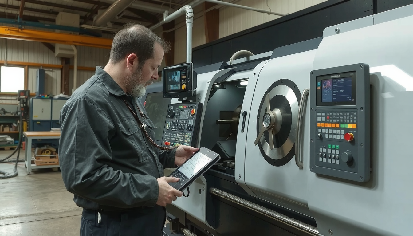
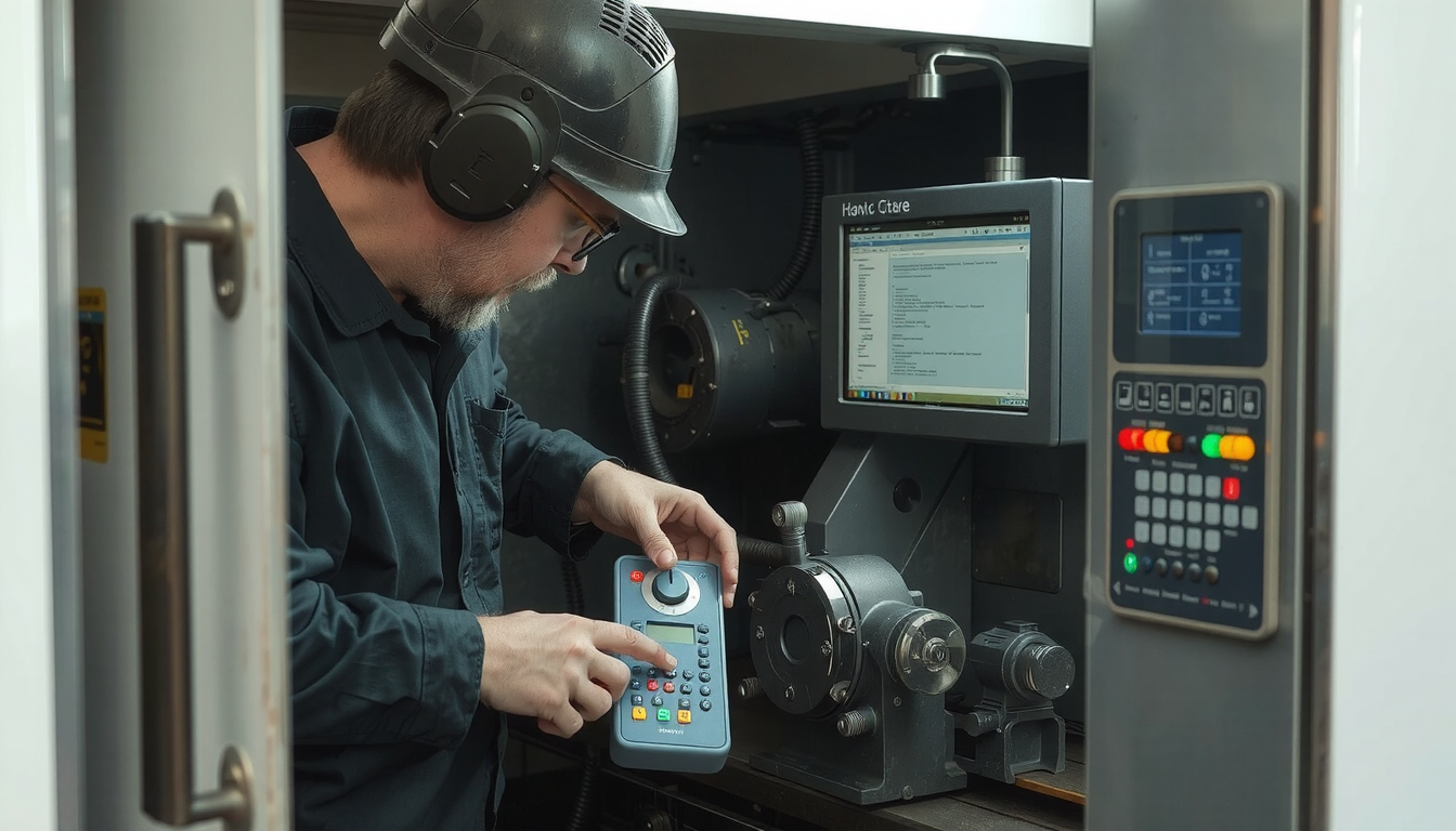
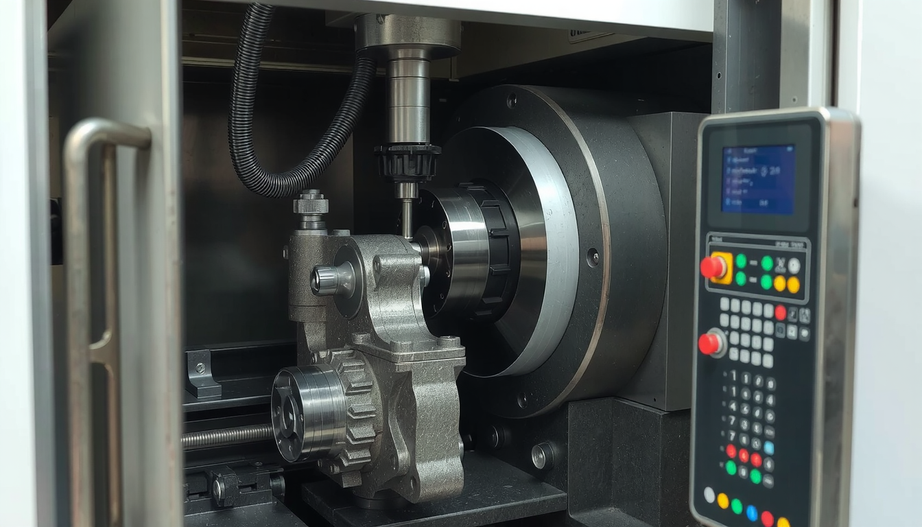
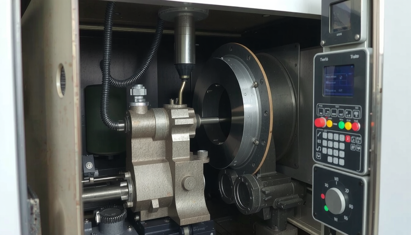
The journey of programming a CNC lathe is as evident as ABC. It involves careful arrangement, key commands, and crucial safety regulations. This manual is your navigation tool. Within the context of this guide, the starting point is the main ideas, the endpoint is your first simple program.

In modern settings, manufacturers usually employ CAD software to produce intricate components. On the contrary, getting acquainted with G-code basics as well as manual programming is a key skill that will forever be needed. This will, in turn, help you become a more efficient machinist and problem solver.
In the course of this guide, you will:
* be introduced to the motion concept of lathe machine and the coordinate system.
* learn the most significant G-codes and M-codes you will use.
* familiarise yourself with the step-wise creation of a program starting from a drawing.
* read a real example program explaining each line in detail.
* know the important safety tips and practical ideas to follow.
At Mekalite, we strongly believe that mastering these principles is the basis for performing quality machining work.
The Principle Concepts: Before You Start Writing Code
Before we proceed with any coding, we need to acknowledge the way the machine perceives things. Grasping these essential concepts first will in a great way facilitate the process of programming a CNC lathe.
Having a Background in CNC Lathe Coordinate System
A CNC lathe usually mainly has two axes (directions). If you look at it in the shape of a graph, it is akin to one that illustrates the part you are working on.
- The Z-axis goes through the center of the rotating part and determines length. Moving towards the chuck is Z-negative. Moving away from the chuck is Z-positive.
- The X-axis moves out and in from the center and determines the diameter. Moving towards the center is X-negative. Moving away from the center is X-positive.
| Axis | Direction | Controls |
|---|---|---|
| X | Up and Down | Diameter |
| Z | Left and Right | Length |
This is a trend-setting simplistic movement system.
What is Part Zero?
Part Zero is the initiation point for all your measurements. It is a single point on a workpiece designated as X0 and Z0 (X and Z both being 0). The machine computes all coordinates referred to in the program based on this point.
In most lathe jobs, we usually see Part Zero to be positioned at the face of the finished part.
The correct statement of this point is very important. If, for instance, you set your Part Zero at a wrong place, the machine will end up cutting the part in the erroneous place. Always remember to double-check your coordinates.
Manual Programming as Against CAM Software

This guide is centered on manual programming. This means you will write the G-code by hand, which is a line-by-line exercise. It is the best way to get to know how the CNC machine functions in reality.
The other method is CAM, that is Computer-Aided Manufacturing. CAM software basically takes a 3D model and automatically generates G-code for you.
Writing codes by hand is a very useful option. It allows you to modify the machine’s program. You will be able to troubleshoot as well as understand what the machine is doing by what you programmed.
Understanding the Keys Involved: Major G-Codes and M-Codes
The codes we are using are the ones we command the machine when we want the machine to perform some task. The codes are quite simple commands. G-codes typically are responsible for movements while M-codes are responsible for operations like the spindle on or off. Thus, the first thing you need to begin programming a CNC lathe is mastering these languages.
Here are the codes which you will often use:
Main Movement G-Codes
These ones are the ones that instruct the tool on how to move.
| Code | Name | Function |
|---|---|---|
| G00 | Rapid Move | Moves at the fastest speed to a desired position. It is not for cutting. |
| G01 | Linear Move | It is used for cutting the tool moving in a straight line at a given feed rate. |
| G02 | Circular Move (CW) | A clockwise arc where the tool moves cut a radius. |
| G03 | Circular Move (CCW) | Counter-clockwise motion of the tool arc to cut a radius. |
Machine State G-Codes
These ones are responsible for the conditions in which the machine is run.
| Code | Name | Function |
|---|---|---|
| G20/G21 | Inch / Metric | The machine is set to read inches (G20) or metric (G21). |
| G96/G97 | Constant Surface Speed | G96 is a variable RPM function that keeps the speed constant. G97 is a fixed RPM. |
| G98/G99 | Feed per Minute/Rev | G98 sets the feed in distance/minute. G99 sets the feed in distance/revolution. |
Common M-Codes (The On/Off Switches)
You can regard these as the light switches of your machine.
| Code | Name | Function |
|---|---|---|
| M03/M04 | Spindle On | M03 is a spindle on in the clockwise direction. M04 is counter-clockwise. |
| M05 | Spindle Stop | Stops the spindle from running. |
| M08/M09 | Coolant On/Off | M08 is coolant on while M09 is coolant OFF. |
| M02/M30 | End of Program | End of the program. M30 is the most common. It resets to the start. |

A more comprehensive list of codes that would fit your controller could be found in the user’s manual. You may also check this ultimate guide provided by Mitsubishi Electric.
The 7 Steps Programming Workflow
The programming process is more about mapping out each step than just writing the code. Following this workflow is your best bet against errors. It makes the program on how to use a CNC lathe much easier to follow. For each part, we apply this procedure which consists of 7 steps.
- Study the Blueprint. Dissect the drawing step by step. Take note of every dimension, corner, and angle. Understand the expected outcome for the final part.
- Organize the Sequence of Operations. Decide which cuts come first. A popular order is part facing first. Then rough turning the outside. Then finish turning, etc. An ordered logical plan is an efficient one.
- Select Tooling. Identify the right tool for each machining operation. The tool used in roughing is different from the one used in finishing. List out the tools you will be using.
- Find Work & Tool Offsets. This is a key machine setup. You will state to the machine your Part Zero (G54). Then, determine the gauge location for each tool tip.
- Make the Program. It is the right time to write the G-code. On the base of your plan, translate step 2 into the code block by block. Be slow and think about every movement.
- Verify & Simulate. Check your work before cutting any metal. Use the graphics mode on the machine (a “dry run”) to see a simulated tool path. Resolving errors in this way is a lot preferable to an actual collision.
- Setup and Run Safely. Load your material and your program. For the first run of a new program, use “Single Block” mode. This stops the program after each line. Always keep your hand on the feed hold button, just in case.
Your First Program: A Practical Walkthrough
Theory is good, but practice is better. Let’s apply everything we have learned to see how to program a CNC lathe for a simple part.
The Project: We will take a 2-inch diameter aluminum rod. We will face the front to make it clean and flat. Then, we will turn the outside diameter down to 1.8 inches for a length of 1 inch.
The Full Program Code
Here is the complete program. The text in parentheses are comments that the machine ignores. They are there to help us understand the code.

“`gcode
O0001 (MY FIRST LATHE PROGRAM);
N10 G20 G40 G99 (SAFETY BLOCK: INCH, CANCEL COMP, FEED/REV);
N20 G28 U0 W0 (SEND TO HOME POSITION);
N30 T0101 (SELECT TOOL 1, OFFSET 1 – ROUGHING TOOL);
N40 G50 S2500 (SET MAX SPINDLE SPEED 2500 RPM);
N50 G96 S400 M03 (CONSTANT SURFACE SPEED 400, SPINDLE ON CW);
N60 G00 X2.1 Z0.1 M08 (RAPID TO START POSITION, COOLANT ON);
(FACING OPERATION);
N70 G01 X-0.06 F0.008 (FEED ACROSS THE FACE);
N80 G00 Z0.1 (RAPID BACK FROM FACE);
N90 X2.1 (RAPID UP);
(ROUGH TURNING OPERATION);
N100 G00 Z0.05 (RAPID TO START OF TURN);
N110 G01 X1.8 Z-1.0 F0.012 (TURN OD TO 1.8″ FOR 1″ LENGTH);
N120 G00 X2.1 (RAPID AWAY FROM PART);
N130 Z0.1 (RAPID BACK);
N140 G28 U0 W0 M09 (GO HOME, COOLANT OFF);
N150 M05 (SPINDLE OFF);
N160 M30 (END PROGRAM AND RESET);
“`
Breaking Down the Code
Let’s look at the program section by section.
The Header (Lines N10-N60): This is the setup part of the program.
* N10 is a safety line that sets the machine to known, safe states.
* N20 sends the machine to its home position.
* N30 calls Tool 1 with its matching offset.
* N40 is a key safety command. G50 sets a maximum spindle speed. When using G96 (Constant Surface Speed), the RPM will increase as the tool moves to a smaller diameter. G50 prevents the chuck from spinning dangerously fast.
* N50 turns on Constant Surface Speed and starts the spindle.
* N60 rapidly moves the tool to a safe spot just in front of the part and turns on the coolant.
The Facing Operation (Lines N70-N90): This makes the front of the part flat.
* N70 is the cutting move. It feeds the tool (G01) across the face of the part at a feed rate of 0.008 inches per revolution.
* N80 and N90 are rapid moves (G00) to pull the tool safely away from the part.
The Turning Operation (Lines N100-N130): This cuts the outside diameter.
* N100 rapidly moves the tool to the start of the cut.
* N110 is the main cutting pass. It feeds the tool along the Z-axis for 1 inch, cutting the diameter down to 1.8 inches.
* N120 and N130 rapidly move the tool up and away from the part.
The Footer (Lines N140-N160): This safely ends the program.
* N140 sends the tool back to its home position and turns off the coolant.
* N150 stops the spindle.
* N160 ends the program and gets it ready to run again.
This is a basic program. As you advance, you will use advanced programming concepts like tool nose compensation (G41/G42) for higher precision.
Conclusion: Start Simple, Program Safe
You now have the basic knowledge of how to program a CNC lathe. It is an achievable skill that opens up a world of making things. The key is to build a strong foundation.
Remember the core principles: Plan your work. Understand the codes. Write your program with care. Always put safety first.
Start with simple parts and use your machine’s simulation mode as much as possible. As your confidence grows, you can tackle more complex jobs.
For complex projects or when you need guaranteed precision and efficiency, partnering with experts can be the best solution. Explore our professional CNC lathe services to see how we can bring your designs to life.
Frequently Asked Questions (FAQ)
1. What’s the main difference between G-code and M-code?
G-codes (Preparatory codes) tell the machine how to move or what state to be in. For example, G01 is a linear feed move. M-codes (Miscellaneous codes) are like on/off switches. They control hardware like the spindle (M03) or coolant (M08).
2. Can I learn to program a CNC lathe without a machine?
Absolutely. Many free or low-cost CNC simulation programs are available. They let you write, test, and see your programs run in a virtual space. This is a very safe and effective way to learn without any risk of damaging a real machine.
3. What is the most common mistake beginners make?
A very common and dangerous mistake is mixing up G00 (rapid move) and G01 (feed move). Moving the tool into the part with G00 will cause a crash. It can damage the tool, the part, and the machine. Always double-check your motion commands before running a program.
4. What are G96 and G97, and when should I use them?
G97 (Constant RPM) sets a fixed spindle speed, like 1000 RPM. It is used for operations like drilling or threading. G96 (Constant Surface Speed) is smarter. It automatically adjusts the RPM as the diameter changes to keep the cutting speed at the tool tip the same. G96 is better for facing and turning because it improves tool life and surface finish.
5. What are canned cycles in CNC lathe programming?
Canned cycles are powerful shortcuts. They let you perform a complex operation with just a few lines of code. For example, a G71 roughing cycle can remove a lot of material automatically. You define the final shape, and the cycle figures out all the individual passes. For a deeper dive, CNC Cookbook provides excellent examples of turning cycles.

