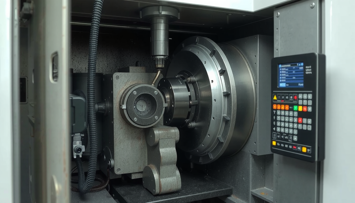
One of the most important skills you will need as a machinist is to learn how to program a radius on a CNC lathe. You will employ circular interpolation G-codes in doing this. These commands are the ones that direct the machine to follow a curved path rather than a straight line.

There are two principal commands: which generates a clockwise arc and for a counter-clockwise arc. To use them, three main elements are required by the machine. It has to know the start point of the arc from the current position of the tool. The machine also has to know the end point coordinates of the arc and its size, that is, the arc size.
There are two ways to define the arc size: either as a straight radius value or the more specific center-point vectors, and . The following is a step by step guide. You will become familiar with the commands that are simple and the most crucial points you need to take note of for you to make the right parts all the time.
The Principal Commands: Concepts of G02 and G03
To program any arc or radius, you should always start with or . These codes instruct the controller to switch from straight-line cutting () to circular cutting. They are the primary means of understanding how to carry out the task of programming a radius on a CNC lathe.
G02 – Clockwise Circular Interpolation
The command specifically directs the tool to go in a clockwise arc. The path starts from the current position of the tool and will finish at the coordinates you specify in the same code line.
G03 – Counter-Clockwise Circular Interpolation
In contrast, the command tells the tool to move in a counter-clockwise arc. This track also traverses from the current position to the specified end point.
Direction Visualization
If you can see the movement of the machine, you will be able to figure out whether to use or . Picture looking down the spindle of a standard CNC lathe from the tailstock toward the chuck. You can easily note, by the view, whether the tool has to move clockwise or counter-clockwise to create the shape you want.
| G-Code | Name | Function |
|---|---|---|
| G02 | Clockwise Interpolation | Moves the tool along a clockwise arc. |
| G03 | Counter-Clockwise Interpolation | Moves the tool along a counter-clockwise arc. |
The Arc Definition: Two Techniques for Programming a Radius
After you have selected your path with or , it is time you choose the arc’s profile. The CNC controller provides two general methods for this task. The first is with the only address or the more advanced and address method.

Method 1: The Simple ‘R’ Address
The simplest option to arc is to utilize the address. In the G-code block, you just have to enter the radius of the arc that you want to cut. A line of code typically appears as the following: .
This command states that the machine will be creating a clockwise arc by ending at X2.5 and Z-1.0 with a radius of 0.25 inches. This is an efficient and effective method when creating simple 90-degree arcs.
Nevertheless, the address has its restrictions. In the case of the arcs that are 180 degrees, the controller might not know which way to proceed. For the arcs exceeding 180 degrees, sometimes the controllers require you to employ a negative value. Referring to a Quick G-Code Arc Tutorial [Make G02 & G03 Easy] – CNC Cookbook, the use of a negative R value is a command that generates the longer arc path between the two points.
Method 2: The Precise ‘I’ and ‘K’ Vectors
In case of extreme precision and clarity, it is best to operationalize the and vectors. These addresses mark the very position of the arc’s central point. They serve to indicate the vector distance and angle from the start of the arc in the center.
refers to the X-axis vector, while is for the Z-axis.
An example of a code block for this method is: . The use of these vectors is markedly appropriate for shapes that must be plotted or perforated with any variation or demand more than just a basic geometric shape.
Choosing Between R vs. I/K Method: a Practical Comparison
Determining the right technique relies on the specifications of the task given. For speed and simplicity, the address remains an option. On the other hand, the and method is a great deal more valuable when it comes to the precision and complexity of geometry. This realization marks a very significant leap in your ability to program a radius on a CNC lathe successfully.
| Feature | ‘R’ Address Method | ‘I’ and ‘K’ Vector Method |
|---|---|---|
| Simplicity | Very easy for simple 90-degree arcs. | More complex, requires calculating the center point. |
| Use Case | Best for corner rounding and simple profiles. | Necessary for arcs not at 90 degrees, full circles, and complex shapes. |
| Ambiguity | Can be unclear for 180° arcs. Some controls cannot make arcs over 180°. | No ambiguity. Mathematically precise. |
| Control | Less control over the arc’s center point. | Full control over the arc’s geometry. |
The Role of Tool Nose Radius Compensation (TNRC) Cannot Be Overlooked
The right programming of G-code is only fifty percent of your job. To effectively machine paper, you have to apply the Tool Nose Radius Compensation (TNRC). Not doing this is one of the common faults and results in a lot of money being lost in CNC lathe programming.

Why Is TNRC Crucial in the Making of Radii?
Your G-code program lays down a path where you will use a point that is sharp and precisely set up. Unfortunately, the actual tool insert you are using is not. It is kind of round with a little curvature which is called the tool nose radius.
This physical property being without compensation leads to mistakes. For example, when you are using the external radius (the corner of a shaft), then the resultant part will be a bit bigger than the specified one. Also, the use of an internal radius (like a fillet in a bore) will introduce a too-small final radius.
I often have seen the starters program a perfect radius and after that, they find out that the part is XYZ and he did not pass the inspection. The arc looks wrong since the radius of the tool itself was not taken into account. This is the saving grace of TNRC.
Activating TNRC through G41 and G42
TNRC changes the tool path automatically to the path of tool nose radius compensation. You will turn it on using or .
- stands for Tool Nose Compensation Left.
- Tool Nose Compensation Right.
A general rule of thumb is to use for most of the outside diameter (OD) turning and for most of the inside diameter (ID) boring. These commands are described in detail in resources covering Lathe Contour Programming.
As far as it goes, for TNRC to function, there are two things that have to be told to the machine in the tool offset page. The first one is that you have to record the tool’s nose radius (for instance, it could be 0.0312″ or 0.8mm). The second thing is that you should also mention what kind of tip it has (such as type 3 which is for a standard OD turning tool).
Example Code of Compensated One
You should activate TNRC before starting the cutting process of the profile, and turn it off after you are done. The command to turn off the tool nose compensation is .
Let’s look at a simple example:
Step-By-Step Examples: Programming a Radius on a CNC Lathe

Theory is important but practice prevails. Let’s have real examples that span how to write a code for a radius on a CNC lathe for common features.
Example 1: Programming an External Convex Radius (OD Turning)
In this practical session, we will create a corner with a 0.125″ radius on a shaft with a diameter of 2 inches using simple address commands.
- Description: First, the face is cut, then the diameter is turned, and lastly, the corner is rounded.
- Code:
Example 2: Programming an Internal Concave Radius (ID Boring)
This case will use an inner bore with a 0.06″ fillet. This is a great feature for additional strength at a corner.
- Description: Bore a straight wall and then create a concave radius at the back.
- Code:
Example 3: Programming a Full Nose Radius on the Face
In this case, a full 180-degree radius is created on the bar end which is the same as the round nose pin. The / method is needed here since an address would be uncertain.
- Description: Start in the center (X0) and cut a 180-degree arc to full diameter.
- Code:To check more examples and learn about the concept of diameter vs. radius programming, feel free to look at CNC Lathe Programming for Turning.
For More Complicated Geometries: CAM Systems and Professional Services
The ability to handwrite the G-code program is a principle skill. It will give you a comprehensive overview of how a machine operates, thus you will be able to control it fully. However, for hard profile components or products that have a lot of blended arcs, hand programming might take more time and is risky.
This is where CAM (Computer-Aided Manufacturing) software becomes the hero. Through the use of CAM systems, you will only need to draw a part and this software will produce the complex toolpaths automatically for you. This is much faster, safer, and more efficient for difficult jobs. For people coming from the manufacturing sector interested in expanding their knowledge on modern technologies, a comprehensive resource exploration like Mekalite could be of value.
On the other hand, for businesses needing cutting-edge components but can’t afford hiring in-house CAM guys, an alternative has developed. Getting into a partnership with a reliable manufacturing firm makes perfect business sense. Involving their specialized CNC lathe services for the complex designs and production orders is the best way to go about it, as they have state-of-the-art CAM software and talented machinists who are able to deal with any configuration.
FAQ: How to Program a Radius on a CNC Lathe
Here are answers to some commons queries that arise frequently about programming radii on a CNC lathe.
Q1: What is the most common radius programming error?
A: Most frequent errors involve reversing direction ( when it probably should have been ) or the Tool Nose Radius Compensation(/) not being applied. Forgetting compensation is the major culprit, and so the radius of the finished part ends up increased or decreased accordingly.
Q2: My machine has shown “Invalid Radius” or “Arc Center Error.” What are they signifying?
A: These errors usually occur when the address is in use. It means the machine is unable to make an arc of the radius you indicated that connects your start and end point. You should be on the lookout for mistakes in the X and Z coordinates of your end point. Very often, selecting the and method to overcome the problem works since it is more exact.
Q3: Is it necessary to run G01 before G02 or G03?
A: It is not something that has to be done, but it is customary. Both and are modal along with (Linear Interpolation). Most of the time, is used to feed the tool to the starting point of the arc. Then you must also remember to switch back to for any straight-line cuts after the arc has finished.
Q4: Can I program a radius using a controller that does not employ G-code?
A: Yes, a number of the up-to-date CNC controllers adapt conversational programming alongside built-in cycles. These graphical interfaces will allow you to choose a corner radius and simply input that you want a radius of a specified size. The control will then generate all relevant G-code for you. However, it is very significant to understand the G-code since it is the foundation for troubleshooting and programming advanced tasks.
Q5: How are radius and diameter programming on a lathe different?
A: This is a fundamental machine setting. In diameter programming mode (the most common), all X values refer to the part’s diameter. In radius programming mode, all X values refer to the part’s radius. An X value of 2.0 means a 2-inch diameter in one mode but a 4-inch diameter in the other. Always be aware of which mode your machine is in.

