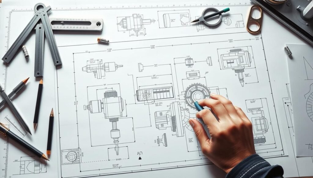
Learning to read technical drawings is key for those in CNC machining and custom metal stamping. These drawings are the blueprints for making things with precision. They give important details and needs for each part. Getting good at this skill makes work better and helps teams talk better.
This article will show you the main parts of technical drawings. It will help you understand how to work with these important documents in making things.
Key Takeaways
- Technical drawings are critical for accurate CNC machining.
- Clarity in drawings can significantly improve production efficiency.
- Understanding custom metal stamping requires familiarity with technical specs.
- Communication between teams hinges on precise drawing interpretation.
- Improperly read drawings can lead to increased errors in manufacturing.
Understanding the Importance of Technical Drawings
Technical drawings are key in CNC machining. They act as a blueprint that outlines the design and needed specs for making things. They make sure everyone knows what to do, making production smooth and accurate.
Role in CNC Machining
CNC machining uses technical drawings to turn designs into real products. These drawings are crucial for making things precise, like in aerospace where details are very small. This shows how important good drawings are for making things right.
Communication Between Designers and Machinists
Good communication is key to avoid mistakes in making things. Technical drawings help designers and machinists understand each other. Without clear drawings, mistakes and delays can happen.
Think about how technical drawings affect CNC machining next time you see them. They help make projects precise and of high quality. For better CNC machining, check out precision CNC machining services for more info.
What is a Technical Drawing?

A technical drawing is key for engineers, designers, and machinists. It shows important details about an object or part. It’s a detailed, precise drawing that shows the design and how it will be made.
The purpose of blueprints is to share this information clearly. This way, everyone knows what needs to be done.
Definition and Purpose
A technical drawing aims to show the exact details of a design. It includes dimensions, materials, and how it will be made. This helps avoid mistakes during production.
Blueprints do more than just show designs. They guide the whole manufacturing process. They help make decisions and ensure everything is made right.
Key Features of Technical Drawings
Knowing what makes technical drawings important helps them work better. Important parts include:
- Dimensions: Clearly show sizes and measurements for a perfect fit.
- Tolerances: Show how much a part can vary without losing quality.
- Annotations: Add extra details like materials and notes for a full understanding.
- Views: Show different angles, like orthographic and isometric, to show the part’s shape.
Anatomy of a Technical Drawing

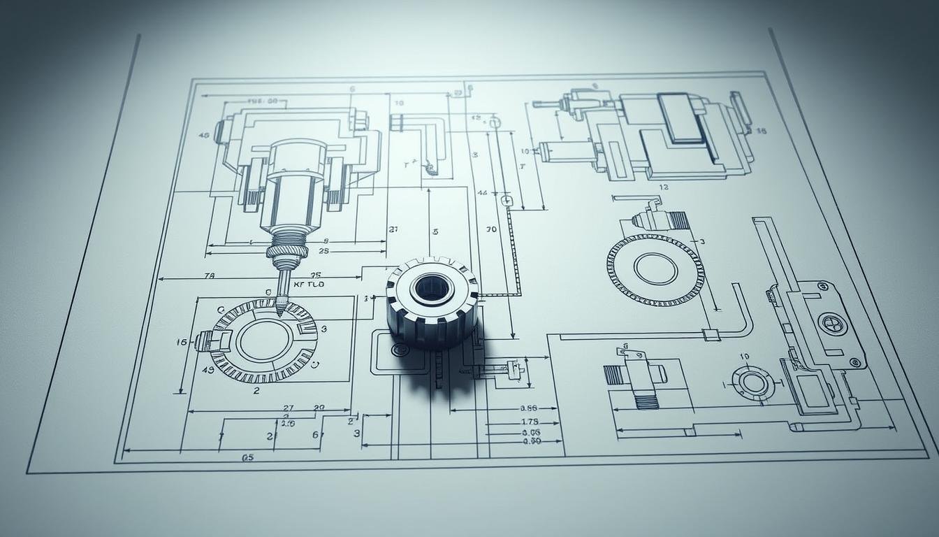
The anatomy of a technical drawing is key for accurate CNC machining. Knowing the parts helps make sure the design is clear to everyone involved.
Title Block Components
The title block is a vital part of technical drawings. It has:
- Part name
- Material specifications
- Scale of the drawing
- Designer details
- Date of creation
Main Orthographic and Isometric Views
Main orthographic views show a clear, two-dimensional view of the object. They help understand dimensions and how parts fit together. Isometric views give a three-dimensional look, showing depth and layout well. Both are needed to fully grasp the design.
Section and Detail Views
Section views show the inside of a part, helping to see how it works. Detail views focus on specific areas that need more explanation. These views help understand complex designs better.
Why Technical Drawings are Important for Custom Metal Stamping

In the custom metal stamping world, technical drawings are key. They set the rules for making parts. These drawings guide engineers and machinists through the making process.
As designs get more complex, the need for precise drawings grows. This shows how important they are for making top-quality products.
Understanding Tolerances and Specifications
Technical drawings must be clear. Every detail, from size to material, affects how parts are made. Specifying tolerances means parts are made within certain limits, usually +/- 0.005 inches.
Knowing these limits and following geometric dimensioning and tolerancing helps make parts accurate.
Reducing Errors in Production
Good technical drawings help avoid mistakes in making parts. They give clear instructions and detailed pictures. This helps keep the making process on track.
Any confusion in designs can cause big problems. So, it’s vital to follow best practices in making these drawings. This ensures every part meets customer needs and industry standards.
Essential Symbols and Lines in Technical Drawings

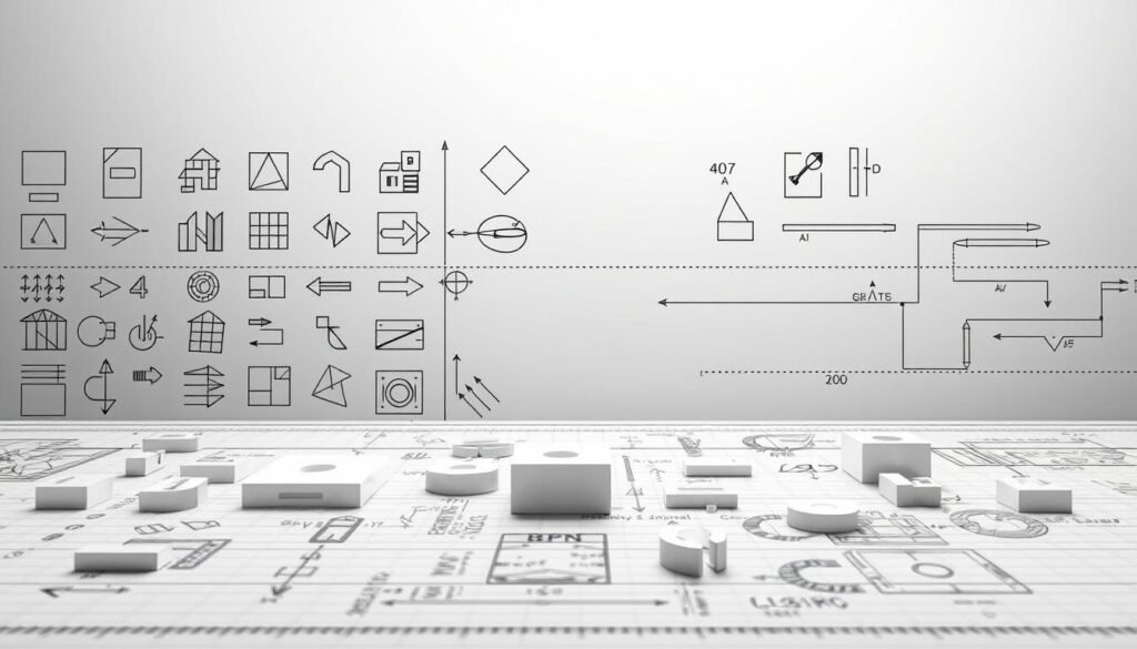
Knowing the symbols and lines in technical drawings is key for correct CNC machining. These symbols are a common language for designers and machinists. They help in clear communication and improve the manufacturing process.
Types of Lines and Their Meanings
There are many types of lines in technical drawings, each with its own meaning. Here’s a table showing the most common types and what they mean:
| Type of Line | Description |
|---|---|
| Visible Lines | Show solid edges and surfaces of objects. |
| Hidden Lines | Indicate edges or surfaces not seen in the current view. |
| Centerlines | Mark symmetry and center points for circles and arcs. |
| Dimension Lines | Give measurements and important reference points. |
| Phantom Lines | Show alternate positions or features not in the current view. |
Common Machinist Symbols to Know
Knowing common machinist symbols is also important. These symbols share vital info about a part’s design and function. Key symbols include:
- Surface Finish Symbols: Show the needed surface texture after machining.
- Tolerance Symbols: Set the allowed variation for dimensions.
- Welding Symbols: Tell how and where to weld parts together.
- Geometric Dimensioning and Tolerancing (GD&T): Control part geometry precisely.
Preparing Your Technical Drawing for CNC Machining
Creating effective technical drawings is key in CNC machining. We aim to make clear blueprints that share all needed info. Proper preparation includes several steps for accuracy and clarity.
Steps for Creating Clear Blueprints
Preparing technical drawings needs a systematic approach:
- Define the necessary views that best represent the part.
- Include precise dimensions and tolerances to specify size and fit.
- Annotate any special requirements or notes relevant to production.
Common Mistakes to Avoid in Technical Drawings
Blueprint mistakes can cause production issues. To keep our technical drawings right, we should avoid:
- Omitting crucial details that affect performance.
- Failing to provide accurate dimensions, which can result in misalignment.
- Using unclear annotations that may confuse machinists.
Dimensions and Tolerances in Technical Drawings
Knowing about dimensions in technical drawings is key for precise CNC machining. They show how much a part can vary in size and shape. This part talks about adding important dimensions and the difference between bilateral and unilateral tolerances.
How to Add Critical Dimensions
Critical dimensions need to be clearly shown on drawings. This helps machinists know which sizes are vital for a part’s function and assembly. Here’s how to mark them:
- Use bold lines or different colors to highlight critical measurements.
- Provide accompanying notes to explain the importance of these dimensions.
- Position critical dimensions strategically near relevant features to enhance clarity.
Understanding Bilateral vs. Unilateral Tolerances
There are two main types of tolerances: bilateral and unilateral. They affect how specs are understood by manufacturers:
| Type | Description | Example |
|---|---|---|
| Bilateral Tolerance | Allows variation in both directions from the nominal dimension | ±0.05 mm on a dimension of 10 mm |
| Unilateral Tolerance | Allows variation in one direction only | +0.1 mm/-0 mm on a dimension of 10 mm |
Knowing these tolerance types helps us clearly state our needs. This ensures the quality and consistency of CNC machined parts.
Notes to the Manufacturer: Enhancing Clarity
In CNC machining, notes to the manufacturer are key. They add clarity to blueprints. These notes give important context and instructions not seen in drawings. They cover surface finish, assembly, and material needs.
Importance of Additional Annotations
Technical drawing annotations guide the production process. Without them, mistakes can happen, costing time and money. They are vital for complex designs and tight tolerances.
Using detailed notes improves communication between designers and makers. This makes the production process smoother.
Symbols vs. Text in Notes
Symbols in notes are quicker to understand than text. They are widely recognized and simplify complex ideas. This helps machinists work more accurately and efficiently.
Choosing the right way to communicate in technical drawings is crucial. It ensures clarity and precision in making things.
Conclusion
Learning to read technical drawings is key for those in manufacturing. It helps us talk better and cut down on mistakes. This skill makes our work more efficient, like in custom metal stamping.
Knowing how to read these drawings helps us work well with designers and machinists. It makes our team work better together. We can make sure every part is top quality.
Staying up-to-date in manufacturing is important. It helps us be good at making things. For more info on CNC machining, click here.
FAQ
What is the role of technical drawings in CNC machining?
Technical drawings are like blueprints. They show the design and details needed for CNC machining. This helps everyone involved understand the project clearly.
Why are technical drawings crucial in custom metal stamping?
They set the standards for precision and quality in metal parts. They guide the inspection of finished products. This helps avoid mistakes during production.
What are the key features to look for in a technical drawing?
Look for dimensions, tolerances, and annotations. Also, check for different views like orthographic and isometric. These help understand the part’s shape and how it fits together.
How do I interpret symbols and lines in technical drawings?
Different lines show different things, like solid edges or hidden parts. Knowing common symbols helps you understand the drawings better.
What common mistakes should I avoid when creating a technical drawing?
Don’t miss important details, and make sure dimensions are right. Clear annotations are key for good CNC machining.
What are the differences between bilateral and unilateral tolerances?
Bilateral tolerances allow changes in both directions. Unilateral tolerances only allow changes in one direction. Knowing this ensures parts work as they should.
How can I enhance clarity with notes to the manufacturer?
Add extra notes for things like surface finish or assembly. Using symbols instead of text can make things clearer.


