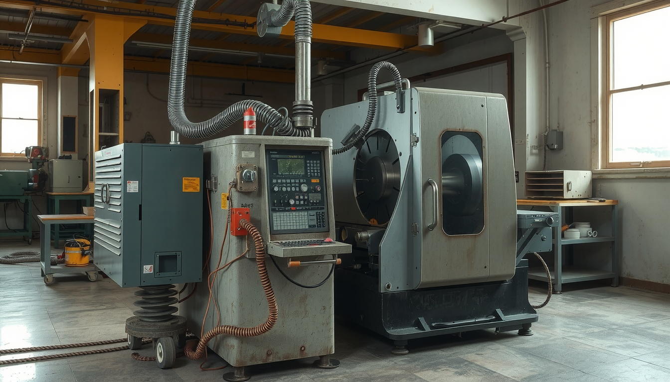
Operating a CNC lathe without proper setup will lead to lots of issues. A good setup ensures safety and makes parts accurately. This manual will help you learn how to set up a CNC lathe correctly if you are a beginner.

This article details the entire process of setup. We will go through safety checks, machine installation, tool installation, and program testing.
Working this way gives you the opportunity to learn and avoid making mistakes. It is also a good way to prevent damage to your machine, tools, or parts. Proper setup is the only road to good machining.
The Build-Block: Pre-Install Safety and Success Checklist
A good setup begins before using the machine. A clean and safe workstation is essential. This checklist helps you avoid common mistakes by ensuring you are ready to work safely. The starting step in learning how to set up a CNC lathe is always safety.
Your 5-Minute Pre-Setup Checklist
- Safety Always First
- Personal Protective Equipment (PPE): Always put on your safety glasses. Wear tough, closed-toe shoes. Stay away from loose clothes, jewelry, or gloves that could get caught in the moving parts.
- Machine State: Be aware of the location of the emergency stop button. Confirm that it will be easily accessible for you. Be ready to use it at all times.
- Documentation and Tooling
- Review the Plan: Go through the job setup sheet or part drawing. Familiarize yourself with the part to be made.
- Gather Tools: Assemble the necessary cutting tools, inserts, and tool holders for the task.
- Gather Measuring Tools: Your calipers, micrometers, and dial indicator are essential for taking accurate measurements.
- Workspace Cleaning
- Clean the Machine: Make use of a brush and air gun to get rid of any chips. Give a good wipe to the chuck, turret, and machine ways. A clean machine reflects accuracy.
- Check Fluid Levels: Confirm that both hydraulic oil and coolant are at the right levels. These low fluids can either damage your machine or produce poor quality parts.
Core Setup Procedure: 5 Steps to Prepare Your CNC Lathe
Below we provide you with detailed steps that will help you set up the machine. Using this process of setup for a CNC lathe will take you from powering on to ready for the first cut.

Step 1: Power-Up and Homing the Machine
To start, switch on the main power breaker. This is usually located on the back of the machine. After this, turn on the power at the control panel.
Then, you have to do a “Machine Zero Return” or “Homing”. This action moves the X and Z axes to a predetermined home position. The machine will utilize the known position as a reference point.
Homing is very crucial. It informs the control of the turret position in its workspace. The rest of the positions are then calculated. The preliminary procedure for starting up is not hard to learn. However, new operators may find it difficult.
Step 2: Installing and Securing Tooling
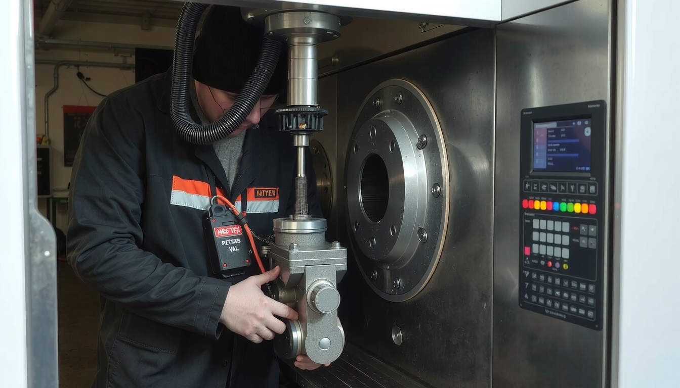
Before inserting the tool holder, clean the turret pocket and holder surfaces. Any small chip or dirt can make the tool misalign.
Securely mount all your cutting tools in their holders. Check that all screws are adequately tightened. The procedure on how to set up a CNC lathe is based on having tools that are strong, and well-fastened.
Try to keep your tool’s overhang as short as possible. If a tool sticks out from the holder, it will vibrate more. This can lead to poor surface finish and can break the tool. Different turret and tool holder setups exist. Always check your machine manual for specific instructions.
Step 3: Mounting and Aligning the Workpiece
Materials can be held in several ways. The most frequently used are 3-jaw chucks, 4-jaw chucks, and collets. Typically, a 3-jaw chuck is used for most jobs.

Fit the stock into the jaws of the chuck and lock it by clamping it. Make sure you have enough material in the jaws to get right on the good rule, which suggests that the clamp length ought to be at least one and a half times the diameter.
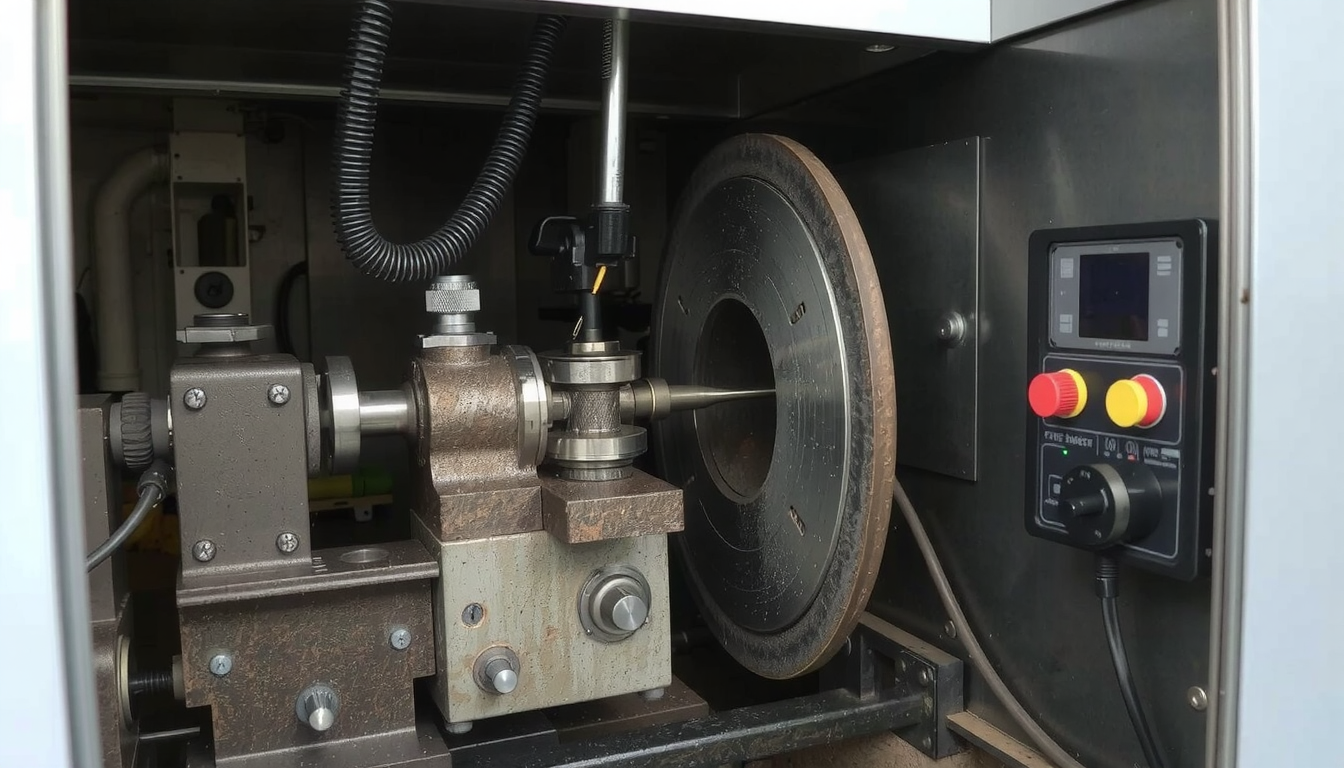
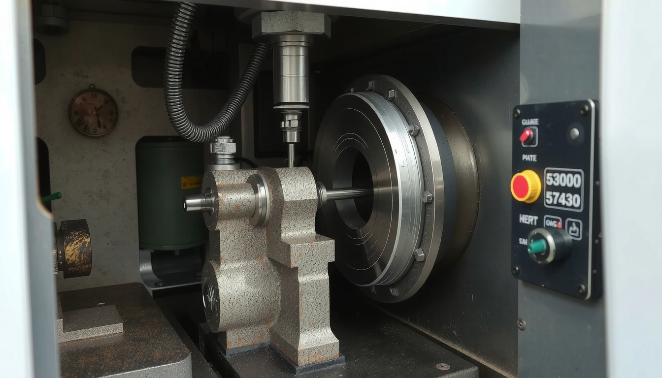
After that, check for “runout”. This is the wavering sound made by the part as it rotates. Use a dial indicator placed against the outer wall of the stock. Hand-rotate the chuck and watch the needle. Align the part until the runout is as small as possible. Proper mounting and centering of the workpiece is the first rule in any accurate lathe setup.
Step 4: Setting Tool and Work Offsets (The “Zero Points”)
This step gives the machine two things. First, the exact position of your tool tips. Second, the location of your workpiece. You can think of it as setting starting and end points on a GPS where you are going on a trip. CNC lathe setup, which is correct, depends on these zero points.
We use a “touch-off” method to set tool geometry offsets. Move the tool with the jog slowly toward the outer diameter of the rotating workpiece. Let the tool make a very light cut, then stop the spindle, carefully measure the diameter you just cut. Enter this number in the X-axis geometry offset page for that tool only.
Following that, repeat the same process for the Z-axis. Carefully bring the tool to the face of the part. A piece of paper can be used to feel the contact. When the tool is making contact with the face, tell the machine this is Z zero for that tool. Do this for each tool you plan to use. Some shops have automated tool presetters that do this work faster.
To set the work coordinate system (often G54), you must establish the “Part Zero” for the Z-axis. This, normally, is the finished front face of the part. Place a known tool (for example, Tool 1 which you just set) against the front of the raw stock. Go to the G54 work offset page and let the machine know that at this precise position there is Z zero. That way the machine is aware of the front side of the part.
Step 5: Loading and Verifying the Program
Load your G-code program into the control of the machine. This can be done using a USB drive or network.
Before you start cutting any metal, you need to verify the program. This can be done by running a “Dry Run”. A “Dry Run” means running the entire program with tools that are far away from the part. They cut only air. You will then view the resulting graphical representation on the screen, showing the expected tool paths.

This step is very important. Running a quick five-minute dry run may save thousands of dollars in damage due to a programming error or wrong offset. It is the last check in the process of how to set up a CNC lathe.
Troubleshooting Common CNC Lathe Setup Errors
Even the best machinists may face problems. The ability to identify the problem is essential. This section covers some common issues you may face while setting up a CNC lathe.
| Problem | Likely Cause(s) | Solution(s) |
|---|---|---|
| Part dimensions consistently off | Tool offset was incorrect; The tool is worn down due to cutting. | Re-measure the tool offset (“re-touch off”); Adjust the wear offset value for that tool. |
| Poor surface finish, or a loud chattering sound | The tool is sticking out too far from the holder; The cutting speeds/feeds are wrong; The cutting insert is dull. | Shorten the tool in the holder to increase rigidity; Check the program for correct speed and feed rates; Rotate or replace the cutting insert. |
| Center drill breaks or the main drill goes off-center | The tool turret is not perfectly aligned; The workpiece has too much runout (wobble). | Check for turret alignment (this may need a service technician); Re-indicate the part in the chuck to get it centered. |
| Machine alarms with the “Over Travel” error | A limit switch is covered in chips or stuck. | Shut down the machine safely. Find the limit switch associated with that axis and clean it carefully. |
Running the First Part: Safety Check First
The setup of a CNC lathe is now finished, and you can start making the first component. This is an incredibly important moment that requires your full attention. Follow these steps to ensure the safe execution of the first piece.
- Set the rapid override knob down at 25%. This effectively slows down all the non-cutting moves and gives you more time to react.
- Use the “Single Block” mode. The machine stops after every single line of code. You should only press “Cycle Start” to move to the next line. Run this for the first tool’s approach.
- Place your finger near the “Feed Hold” button. You should be ready to stop the program immediately if you see or hear anything wrong.
- Watch and listen. Pay special attention to the sound of the cut you are making. A smooth hum means everything is good. A loud screech or vibration is bad.
- After the first part is done, measure the dimensions accurately. If the figures come to a little change, use your wear offsets to make small adjustments for the next part.
Conclusion: The Key is Setup in Precision Machining
Setting a CNC lathe, thus, is the key to all the faults including successful work. These steps will become second nature with practice. That means they will be easy and quick to do. This structured procedure is a guarantee for safety, accuracy, and efficiency at all times.
Use cnc lathe services if you have very complex jobs or large production runs because they can deliver the absolute best results. Check Mekalite to explore advanced machining and manufacturing solutions.
Frequently Asked Questions (FAQ) about CNC Lathe Setup
Which is most important in setting up the CNC lathe?
All of the steps are critical. However, the most crucial is setting the work and tool offsets correctly. The main reason for scrapped parts and crashes is the wrong offset. It is good always to double-check these parameters before starting.
When should I check my tool offsets?
You should set the offset for every new tool that you add to the machine. For tools that are already in use, check them at the start of a new shift or after making a number of parts. Tool wear can cause inaccuracies in parts. Also, a worn offset should be checked if you notice the part sizes changing.
What is the difference between a tool geometry offset and a wear offset?
The Geometry offset measures the distance from the machine’s home position to the tool’s tip. This is set once when the tool is new. The Wear offset is made during a job to account for the tool getting dull and it is just a small adjustment. It allows for correcting sizes without changing the main geometry number.
Can I use the same setup for various materials?
Not totally. The physical setup of clamping the part and holder may be the same. But, in almost every case, you will need to write a different G-code program. Different materials require different cutting speeds, feed rates, and sometimes different cutting tools to achieve the desired results.
What does “runout” refer to, and why is it bad?
Runout is when a workpiece wobbles as it is turning. It occurs when the part is not properly centered in the chuck. It is bad because it results in the tool cutting deeper on one side relative to the other. This, in turn, leads to a poor surface finish, incorrect dimensions, and sometimes it can cause tools to vibrate or even break.

